Wireless communication between Electronic devices and modules is very important, to make them ‘Fit’ in the World of Internet of Things. HTTP protocol and HTML language have made it possible to transfer the Data anywhere in the world, over the web. We have already covered some projects which Now in this tutorial, we are building a program to Send Data to Web using Arduino and Wi-Fi module. For this we first need an IP address of either Global or Local server, here for the ease and demonstration purpose, we are using Local Server.
Components Required:
- Arduino UNO
- ESP8266 Wi-Fi Module
- USB Cable
- Connecting wires
- Laptop
- Power supply
Wi-Fi Module ESP8266:
3. In wifi_init() function, we initialize the wifi module by sending some commands like reset, set mode, connect to router, configure connection etc. These commands have also been explained above in description part.
Circuit Connections:
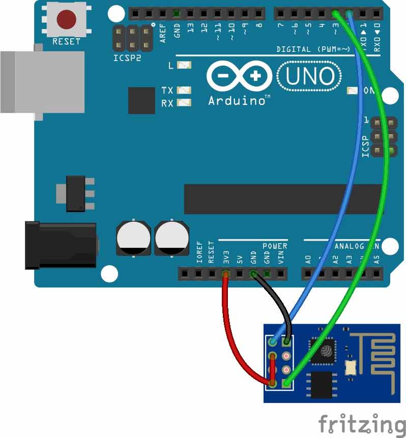
Circuit Diagram for “Post Data from Arduino to Web” is given below. We mainly need a Arduino and ESP8266 Wi-Fi module. ESP8266’s Vcc and GND pins are directly connected to 3.3V and GND of Arduino and CH_PD is also connected with 3.3V. Tx and Rx pins of ESP8266 are directly connected to pin 2 and 3 of Arduino. Software Serial Library is used to allow serial communication on pin 2 and 3 of Arduino. We have already covered

By using Software Serial Library here, we have allowed serial communication on pin 2 and 3, and made them Rx and Tx respectively. By default Pin 0 and 1 of Arduino are used for serial communication but by using SoftwareSerial library, we can allow serial communication on other digital pins of the Arduino.
Note: To watch the response of ESP8266 on serial monitor, please open Serial Monitor of Arduino IDE.
Working Explanation:
First of all we need to connect our Wi-Fi module to Wi-Fi router for network connectivity. Then we will Configure the local server, Send the data to Web and finally Close the connection. This process and commands have been explained in below steps:
1. First we need to test the Wi-Fi module by sending AT command, it will revert back a response containing OK.
2. After this, we need to select mode using command AT+CWMODE=mode_id , we have used Mode id =3. Mode ids:
1 = Station mode (client)
2 = AP mode (host)
3 = AP + Station mode (Yes, ESP8266 has a dual mode!)
2 = AP mode (host)
3 = AP + Station mode (Yes, ESP8266 has a dual mode!)
3. Now we need to disconnect our Wi-Fi module from the previously connected Wi-Fi network, by using the command AT+CWQAP, as ESP8266 is default auto connected with any previously available Wi-Fi network
4. After that, user can Reset the module with AT+RST command. This step is optional.
5. Now we need to connect ESP8266 to Wi-Fi router using given command
AT+CWJAP=”wifi_username”,”wifi_password”
6. Now get IP Address by using given command:
AT+CIFSR
It will return an IP Address.
7. Now enable the multiplex mode by using AT+CIPMUX=1 (1 for multiple connection and 0 for single connection)
8. Now configure ESP8266 as server by using AT+CIPSERVER=1,port_no (port may be 80). Now your Wi-Fi is ready. Here ‘1’ is used to create the server and ‘0’ to delete the server.
9. Now by using given command user can send data to local created server:
AT+CIPSEND =id, length of data
Id = ID no. of transmit connection
Length = Max length of data is 2 kb
10. After sending ID and Length to the server, we need to send data like :Serial.println(“circuitdigest@gmail.com”);
11. After sending data we need close the connection by given command:
AT+CIPCLOSE=0
Now data has been transmitted to local server.
12. Now type IP Address in Address Bar in web browser and hit enter. Now user can see transmitted data on webpage.
Check the Video below for complete process.
Steps for Programming:
1. Include SoftwareSerial Library for allow serial communication on PIN 2 & 3 and declare some variables and strings.
#include<SoftwareSerial.h>
SoftwareSerial client(2,3); //RX, TX

String webpage="";
int i=0,k=0;
String readString;
int x=0;

boolean No_IP=false;
String IP="";
char temp1='0';
2. After this, we have to define some functions for performing our desired tasks.
In Setup() function, we initialise inbuilt serial UART communication for ESP8266 asclient.begin(9600); at the baud rate of 9600.
void setup()
{
   Serial.begin(9600);
   client.begin(9600);
   wifi_init();
   Serial.println("System Ready..");
}
void wifi_init()
{
      connect_wifi("AT",100);
      connect_wifi("AT+CWMODE=3",100);
      connect_wifi("AT+CWQAP",100);
      connect_wifi("AT+RST",5000);
      ...... .....
      ..... .....
4. In connect_wifi() function, we send commands data to ESP8266 and then read response from ESP8266 Wi-Fi module.
void connect_wifi(String cmd, int t){int temp=0,i=0;while(1) {...... .....Serial.println(cmd);..... .....
5. sendwebdata( ) function is used for sending data to Local Server or Webpage.
void sendwebdata(String webPage)
{
    int ii=0;
     while(1)
     {
      unsigned int l=webPage.length();
      Serial.print("AT+CIPSEND=0,");
      client.print("AT+CIPSEND=0,");
      ...... .....
      ..... .....
6. void send() function is used for sending data strings to sendwebdata() function. That will be further sent to webpage.
void Send()
{
      webpage = "<h1>Welcome to Circuit Digest</h1><body bgcolor=f0f0f0>";
      sendwebdata(webpage);
      webpage=name;
      webpage+=dat;
      ...... .....
      ..... .....
7. get_ip() function is used for getting IP address of Local created server.
8. In void loop() function, we send instruction to user for refreshing the page and check whether the server is connected of not. When user refresh or request the webpage, data automatically transmitted to the same IP address.
void loop()
{
  k=0;
  Serial.println("Please Refresh your Page");
  while(k<1000)
  .... .....
  .... .....
We can display any data from Arduino to Webpage using this process, like Room Temperature & Humidity, Clock time, GPS coordinates, Heart beat Rate etc.
code
#include<SoftwareSerial.h>
SoftwareSerial client(2,3); //RX, TX
SoftwareSerial client(2,3); //RX, TX
String webpage="";
int i=0,k=0;
String readString;
int x=0;
int i=0,k=0;
String readString;
int x=0;
boolean No_IP=false;
String IP="";
char temp1='0';
String IP="";
char temp1='0';
String name="<p>Circuit Digest</p>"; //22
String dat="<p>Data Received Successfully.....</p>"; //21
void check4IP(int t1)
{
int t2=millis();
while(t2+t1>millis())
{
while(client.available()>0)
{
if(client.find("WIFI GOT IP"))
{
No_IP=true;
}
}
}
}
String dat="<p>Data Received Successfully.....</p>"; //21
void check4IP(int t1)
{
int t2=millis();
while(t2+t1>millis())
{
while(client.available()>0)
{
if(client.find("WIFI GOT IP"))
{
No_IP=true;
}
}
}
}
void get_ip()
{
IP="";
char ch=0;
while(1)
{
client.println("AT+CIFSR");
while(client.available()>0)
{
if(client.find("STAIP,"))
{
delay(1000);
Serial.print("IP Address:");
while(client.available()>0)
{
ch=client.read();
if(ch=='+')
break;
IP+=ch;
}
}
if(ch=='+')
break;
}
if(ch=='+')
break;
delay(1000);
}
Serial.print(IP);
Serial.print("Port:");
Serial.println(80);
}
{
IP="";
char ch=0;
while(1)
{
client.println("AT+CIFSR");
while(client.available()>0)
{
if(client.find("STAIP,"))
{
delay(1000);
Serial.print("IP Address:");
while(client.available()>0)
{
ch=client.read();
if(ch=='+')
break;
IP+=ch;
}
}
if(ch=='+')
break;
}
if(ch=='+')
break;
delay(1000);
}
Serial.print(IP);
Serial.print("Port:");
Serial.println(80);
}
void connect_wifi(String cmd, int t)
{
int temp=0,i=0;
while(1)
{
Serial.println(cmd);
client.println(cmd);
while(client.available())
{
if(client.find("OK"))
i=8;
}
delay(t);
if(i>5)
break;
i++;
}
if(i==8)
Serial.println("OK");
else
Serial.println("Error");
}
{
int temp=0,i=0;
while(1)
{
Serial.println(cmd);
client.println(cmd);
while(client.available())
{
if(client.find("OK"))
i=8;
}
delay(t);
if(i>5)
break;
i++;
}
if(i==8)
Serial.println("OK");
else
Serial.println("Error");
}
void wifi_init()
{
connect_wifi("AT",100);
connect_wifi("AT+CWMODE=3",100);
connect_wifi("AT+CWQAP",100);
connect_wifi("AT+RST",5000);
check4IP(5000);
if(!No_IP)
{
Serial.println("Connecting Wifi....");
connect_wifi("AT+CWJAP=\"1st floor\",\"muda1884\"",7000);
// connect_wifi("AT+CWJAP=\"vpn address\",\"wireless network\"",7000);
}
else
{
}
Serial.println("Wifi Connected");
get_ip();
connect_wifi("AT+CIPMUX=1",100);
connect_wifi("AT+CIPSERVER=1,80",100);
}
{
connect_wifi("AT",100);
connect_wifi("AT+CWMODE=3",100);
connect_wifi("AT+CWQAP",100);
connect_wifi("AT+RST",5000);
check4IP(5000);
if(!No_IP)
{
Serial.println("Connecting Wifi....");
connect_wifi("AT+CWJAP=\"1st floor\",\"muda1884\"",7000);
// connect_wifi("AT+CWJAP=\"vpn address\",\"wireless network\"",7000);
}
else
{
}
Serial.println("Wifi Connected");
get_ip();
connect_wifi("AT+CIPMUX=1",100);
connect_wifi("AT+CIPSERVER=1,80",100);
}
void sendwebdata(String webPage)
{
int ii=0;
while(1)
{
unsigned int l=webPage.length();
Serial.print("AT+CIPSEND=0,");
client.print("AT+CIPSEND=0,");
Serial.println(l+2);
client.println(l+2);
delay(100);
Serial.println(webPage);
client.println(webPage);
while(client.available())
{
//Serial.print(Serial.read());
if(client.find("OK"))
{
ii=11;
break;
}
}
if(ii==11)
break;
delay(100);
}
}
{
int ii=0;
while(1)
{
unsigned int l=webPage.length();
Serial.print("AT+CIPSEND=0,");
client.print("AT+CIPSEND=0,");
Serial.println(l+2);
client.println(l+2);
delay(100);
Serial.println(webPage);
client.println(webPage);
while(client.available())
{
//Serial.print(Serial.read());
if(client.find("OK"))
{
ii=11;
break;
}
}
if(ii==11)
break;
delay(100);
}
}
void setup()
{
Serial.begin(9600);
client.begin(9600);
wifi_init();
Serial.println("System Ready..");
}
{
Serial.begin(9600);
client.begin(9600);
wifi_init();
Serial.println("System Ready..");
}
void loop()
{
k=0;
Serial.println("Please Refresh your Page");
while(k<1000)
{
k++;
while(client.available())
{
if(client.find("0,CONNECT"))
{
Serial.println("Start Printing");
Send();
Serial.println("Done Printing");
delay(1000);
}
}
delay(1);
}
}
{
k=0;
Serial.println("Please Refresh your Page");
while(k<1000)
{
k++;
while(client.available())
{
if(client.find("0,CONNECT"))
{
Serial.println("Start Printing");
Send();
Serial.println("Done Printing");
delay(1000);
}
}
delay(1);
}
}
void Send()
{
webpage = "<h1>Welcome to Circuit Digest</h1><body bgcolor=f0f0f0>";
sendwebdata(webpage);
webpage=name;
webpage+=dat;
sendwebdata(webpage);
delay(1000);
webpage = "<a href="http://circuitdigest.com/";
webpage+="\">Click Here for More projects</a>";
sendwebdata(webpage);
client.println("AT+CIPCLOSE=0");