المكونات والإمدادات
اردوينو اونو او او جينون
كابل A-B
يمكنك العثور على مخططات دائرة مولد الموجة NE555 في العديد من الأماكن على الإنترنت ، على سبيل المثال. هنا: https://www.physicsforums.com/threads/555-timer-50-duty-cycle-astable-run-from-5v.923687/
ملاحظة: عدد العينات في قواعد الوقت السريع محدود لتحقيق أخذ العينات بسرعة عالية. هذا ما يفسر انخفاض دقة تتبع الإشارة. على قواعد الوقت أبطأ الحل أفضل (انظر أدناه).
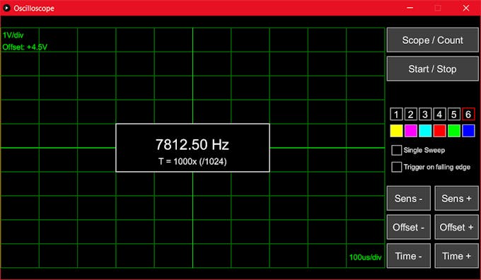
يمكن تغيير الفترة الزمنية للعد عن طريق الضغط على الأزرار "Time-" و "Time +". سيعمل "الوقت +" على زيادة عدد الفترات الزمنية (T) التي يتم حساب معدل تكرارها أو تغيير عامل تقسيم الساعة ("/ 1024" أو "256" أو "/ 64") الذي يحدد الدقة. "/ 64" يعطي أفضل دقة ، ولكن لإشارات الترددات المنخفضة قد تتسبب في حدوث فيض الموقت ، مما يؤدي إلى قراءات خاطئة. "الوقت" يفعل عكس ذلك.
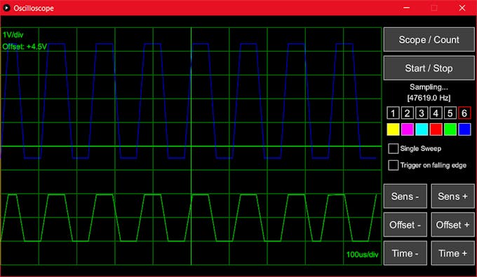
للاختبار ، يمكنك تغيير دورة التشغيل لإشارة PWM Arduino بالضغط على "" - "و" + "على جهاز الكمبيوتر الخاص بك. إذا قمت بتوصيل LED إلى PW ستلاحظ أن سطوع LED يتغي
تحتاج إلى تطبيق يسمى "معالجة" يعمل على جهاز الكمبيوتر الخاص بك. إنه تنزيل مجاني. من السهل العثور عليه باستخدام Google (أو في processing.org). تثبيته ، تحميل ملف * .pde المقدمة مع هذا المشروع وقبالة تذهب. (ملاحظة: قم بتحميل الرمز إلى Arduino أولاً ، ثم ابدأ تشغيل البرنامج لتفادي التعارضات على اتصال USB التسلسلي الخاص بك)
اردوينو اونو او او جينون
كابل A-B
حول هذا المشروع
أردت أن أتمكن من مراقبة الإشارات الكهربائية من الدوائر التي أقوم ببنائها ، لذا احتجت إلى مرسمة الذبذبات. الحل الذي قمت بإنشائه يستخدم Arduino UNO في تركيبة مع معالجة قيد التشغيل على جهاز كمبيوتر.
يتميز كاشف الذبذبات بإمكانية اختيار 6 قنوات (مسامير A0-A5 على Arduino) ، ومدخل تشغيل منفصل مع إعداد الزناد المتصاعد أو الساقط ، وضع المسح المستمر أو الفردي ، وقاعدة الوقت القابلة للتعديل (100us-200s / div) ، والحساسية القابلة للتغيير تعويض لكل قناة. كما أن لديها وضع عداد تردد يقيس تردد إشارة دخل الزناد.
لاحظ أنني أستخدم جهاز ضبط الوقت وقاطع سجلات Arduino UNO مباشرة ، متجاوزًا واجهة برمجة تطبيقات Arduino API ، لذلك لن يعمل الكود على إصدارات Arduino الأخرى دون تغييرات. يرجى التأكد من أنك على دراية بالمؤثرات والمقاطعات قبل تعديل الشفرة.
تحذير: لا تقم بتوصيل الإشارات خارج نطاق 0 إلى 5 فولت مباشرةً إلى مدخلات Arduino الخاصة بك ، لأن ذلك قد يؤدي إلى تلف جهازك بعد إصلاحه!
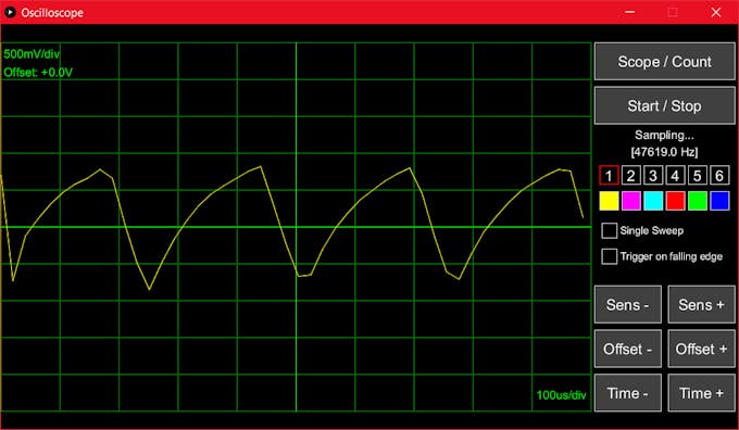
تعرض الصور الموجودة أدناه واجهة المستخدم الرسومية لمنظور الذبذبات على الكمبيوتر. تتحكم الأزرار الموجودة على اليمين في إعدادات النطاق. يؤدي الضغط على أحد الأرقام إلى تغيير قناة الإدخال النشطة ، حيث يؤدي الضغط على مربع ملون إلى تبديل رؤية مسار القناة المعني وإيقافه. لبدء / إيقاف القياس ، اضغط على "بدء / إيقاف". في وضع المسح المفرد ، تحتاج إلى
الضغط على "بدء / إيقاف" في كل مرة تريد فيها بدء عملية مسح جديدة.
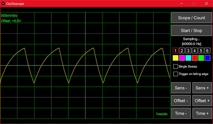
ملاحظة: عدد العينات في قواعد الوقت السريع محدود لتحقيق أخذ العينات بسرعة عالية. هذا ما يفسر انخفاض دقة تتبع الإشارة. على قواعد الوقت أبطأ الحل أفضل (انظر أدناه).
للاختبار ، يمكنك تغيير دورة التشغيل لإشارة PWM Arduino بالضغط على "" - "و" + "على جهاز الكمبيوتر الخاص بك. إذا قمت بتوصيل LED إلى PW ستلاحظ أن سطوع LED يتغي
تحتاج إلى تطبيق يسمى "معالجة" يعمل على جهاز الكمبيوتر الخاص بك. إنه تنزيل مجاني. من السهل العثور عليه باستخدام Google (أو في processing.org). تثبيته ، تحميل ملف * .pde المقدمة مع هذا المشروع وقبالة تذهب. (ملاحظة: قم بتحميل الرمز إلى Arduino أولاً ، ثم ابدأ تشغيل البرنامج لتفادي التعارضات على اتصال USB التسلسلي الخاص بك)
كود البرمجة
/*
   6-channel oscilloscope

  Operation mode:
    '#': frequency counter
    '*': oscilloscope
    '!': reset

   Trigger modes:
    'E': rising edge
    'F': falling edge

   Sweep mode:
    'C': continuous
    'D': single sweep

   Time base:
   100, 200, 500 us
   1, 2, 5 ms
   10, 20, 50 ms
   100, 200, 500 ms
   1, 2, 5 s
   10, 20, 50 s
   100, 200 s

   Timebase is identified by characters 'a'-'t'

   Channel:
   Channels are selected by '0'-'5'

   Counter time base
   'G': 1 period, clock divider 1024
   'H': 1 period, clock divider 256
   'I': 1 period, clock divider 64
   'J': 10 periods, clock divider 1024
   ...
   'U': 10000 periods, clock divider 64
*/

#define ScopeMode '*'
#define CounterMode '#'

#define InitialMode '#'

// Trigger input pin (only 2 or 3)
#define TriggerPin 3

#define MaxSamples 1000

// Pin to connect an LED showing counter measuring intervals
#define CounterPin 4
// Pin to generate a PWM signal (5 or 6 only)
#define PwmPin 6
#define PwmFreq65k 0x1
#define PwmFreq7k 0x2
#define PwmFreq976 0x3
#define PwmFreq244 0x4
#define PwmFreq061 0x5

// Timer and interrupt settings
#define INTBIT B00000001
#define TRIGCLR B00000001
#define TRIGRISE B00000011
#define TIMERCTCA B00000000
#define TIMERCTCB B10001000
#define TIMERCNTA B00000000
#define TIMERCNTB B00000000
#define TIMERNOCLK B11111000
#define TIMERPS0001 B00000001
#define TIMERPS0256 B00000100
#define TIMERPS1024 B00000101
#define ADCINIT B10000111
#define ADCSELECT B01100000
#define ADCSTART B01000000
#define ADCPSCLR B11111000
#define ADCPS016 B00000100
#define ADCPS032 B00000101
#define ADCPS064 B00000110
#define ADCPS128 B00000111
#define ADCREADY B00010000
#define CLEARADIF B10101111

boolean scope = true;

// The interrupt setting depends on the choice of the trigger pin
byte intBit = (INTBIT << (TriggerPin == 2 ? 0 : 1));

// Current mode variables
boolean continuousSweep = true;
byte currentChannel = 0;
char currentBase;

// Sample variables
volatile byte sample[MaxSamples];
byte timerPrescaler;
int samples;
volatile int index;
volatile int writeIndex;

// Frequencey counter current ode variables
int periodCount;
volatile int periods = 0;
volatile unsigned long count;
volatile byte counterDiv = 5;

// PWM output value
unsigned int pwm = 128;

/* Initialize the Analog-Digital Converter */
void initAdc()
{
  ADCSRA = ADCINIT;
  ADMUX  = ADCSELECT;
}

/* Read a sample from the ADC */
void readAdc()
{
  unsigned int result = 0;

  ADCSRA |= ADCSTART; // Start conversion
  while ((ADCSRA & ADCREADY) == 0);
  sample[index++] = ADCH;                       // 8-bit sample size for speed
  ADCSRA &= CLEARADIF;
}

/* Trigger Interrupt Service Routine */
#if (TriggerPin == 2)
ISR(INT0_vect)
#else
ISR(INT1_vect)
#endif
{
  if (scope)
  {
    EIMSK &= ~intBit;
    EIFR |= intBit;

    readAdc();                                    // Read first sample immediately
    TCNT1 = 0;                                    // Reset timer
    TCCR1B |= timerPrescaler;                     // Start timer now
  }
  else
  {
    int c = TCNT1;

    TCNT1 = 0;
    TCCR1B = counterDiv;                          // Start counter
    count += c;                                   // Add current timer to total count
    periods++;                                    // Another period counted
    if (periods > periodCount)                    // If all periods counted for a measurment...
    {
      TCCR1B = 0;                                 // ... Stop counter
      writeCount(count);                          // Report value to PC
      counterReset();                             // Reset counter for next measurement
    }
  }
}

/* Handle the end of a sweep */
void stopSweep()
{
  TCCR1B &= TIMERNOCLK;                           // Set clock select to 0 (no clock)
  index++;
  writeData();                                    // Write sampled data to serial connection
  if (continuousSweep)
  {
    scopeReset();                                 // Restart automatically in continuous sweep mode
  }
}

/* Reset the scope for a new sweep */
void scopeReset()
{
  TCCR1B &= TIMERNOCLK;                           // Stop the timer by setting clock select to 0 (no clock)

  Serial.print((char) 0xFF);                      // Mark end of sweep to console

  index = 0;                                      // Reset sweep data
  writeIndex = 0;

  EIFR |= intBit;                                 // Reset trigger interrupt flag
  EIMSK |= intBit;                                // Enable interrupts on trigger input

  // Wait for trigger signal interrupt
}

/* Reset the frequency counter to start another measurement */
void counterReset()
{
  digitalWrite(CounterPin, HIGH - digitalRead(CounterPin)); // Toggle indicator LED
  periods = 0;                                    // Reset counted periods
  count = 0UL;                                    // Reset total timer counts
  TCNT1 = 0;                                      // Reset timer
  EIFR != intBit;
}

/* Interrupt Service Routine for timer OCR compare match */
ISR(TIMER1_COMPA_vect)
{
  readAdc();                                      // Read next ADC sample and store it
//  if (currentBase >= 'g')                         // On slow time bases, write immediately
//  {
//    writeData();
//  }
  if (index >= samples)
  {
    stopSweep();                                  // Got all samples for this sweep, so end it
  }
}

/* Set the sample time for the selected time base.
 * The selection is done with a single character 'a'-'t'.
*/
void setSampleTime(char c)
{
  unsigned int cnt;

  currentBase = c;                                // Store the time base as current

  ADCSRA &= ADCPSCLR;                             // Clear prescaler
  // Set ADC prescaler
  switch (c)
  {
    case 'a':
    case 'b':
    case 'c':
    case 'd':
      ADCSRA |= ADCPS016;
      break;
    case 'e':
      ADCSRA |= ADCPS032;
      break;
    case 'f':
      ADCSRA |= ADCPS064;
      break;
    default:
      ADCSRA |= ADCPS128;
      break;
  }

  // Set #samples
  switch (c)
  {
    case 'a':
      samples = 48;
//      samples = 46;
      break;
    case 'b':
      samples = 95;
//      samples = 91;
      break;
    case 'c':
//      samples = (50 << (c - 'a'));
      samples = 238;
//      samples = 227;
      break;
      break;
    case 'd':
    case 'e':
      samples = 400;
      break;
    default:
      samples = (c >= 'o' ? 1000 : 500);
      break;
  }

  // Set timer prescaler
  timerPrescaler = (c <= 'j' ? TIMERPS0001 : (c <= 'r' ? TIMERPS0256 : TIMERPS1024));

  // Set counter max value
  switch (c)
  {
    case 'a':
    case 'b':
    case 'c':
//      cnt = 400;
      cnt = 336;
//      cnt = 352;
      break;
    case 'd':
    case 'e':
    case 'f':
    case 'g':
    case 'h':
      cnt = 400 << (c - 'd');
      break;
    case 'i':
      cnt = 16000;
      break;
    case 'j':
      cnt = 32000;
      break;
    case 'k':
      cnt = 250;
      break;
    case 'l':
    case 'm':
    case 'n':
      cnt = 625 << (c - 'l');
      break;
    case 'o':
    case 'p':
    case 'q':
      cnt = 3125 << (c - 'o');
      break;
    case 's':
      cnt = 15625;
      break;
    case 'r':
    case 't':
      cnt = 31250;
      break;
  }
  OCR1A = cnt;
}

/* Set trigger mode to falling or rising edge */
void setTriggerMode(char c)
{
  if (c == 'F')
  {
    EICRA &= ~(TRIGCLR << (TriggerPin == 2 ? 0 : 2));
  }
  else
  {
    EICRA |= TRIGRISE << (TriggerPin == 2 ? 0 : 2);
  }
}

/* Sweep mode (continuous or single) */
void setSweepMode(char c)
{
  continuousSweep = (c == 'C');                   // 'C' is continuous, 'S' is single
}

/* Set the channel '1'-'6' */
void setChannel(char c)
{
  currentChannel = (c - '1');                     // Internally, channels are 0-5
  ADMUX &= B11110000;
  ADMUX |= (currentChannel & 0x7);                // Switch the ADC multiplexer to the channel pin
}

/* Start oscilloscope mode */
void setScope()
{
  scope = true;
  digitalWrite(CounterPin, LOW);                  // Switch off counter indicator
  TCCR1A = TIMERCTCA;                             // Use Timer1 in 'match OCR' mode for sampling
  TCCR1B = TIMERCTCB;                             // No clock, so no interrupts yet
  TIMSK1 |= (1 << OCIE1A);                        // Enable timer1 compare interrupts
  execute(currentBase);                           // Set the time base to the last used
  scopeReset();                                   // Restart scope
}

/* Start frequency counter mode */
void setCounter()
{
  scope = false;
  periodCount = 1;
  digitalWrite(CounterPin, HIGH);                 // Switch on counter indicator
  TCCR1A = TIMERCNTA;                             // Use Timer1 in normal mode for counting
  TCCR1B = 0;                                     // Hold timer
  TIMSK1 &= ~(1 << OCIE1A);                       // Disable timer1 compare interrupts
  EIFR |= intBit;
  EIMSK |= intBit;                                // Enable external interrupt
  counterReset();                                 // Restart frequency counter
}

/* Set the number of periods to count for determining frequency */
void setPeriods(char c)
{
  int s = c - 'G';
  int p = s / 3;                                  // Period count 1, 10, 100, 1000 or 10000
  counterDiv = 5 - (s % 3);                       // Clock divider 64, 256 or 1024 for accuracy
  periodCount = 1;
  for (int per = 0; per < p; per++)
  {
    periodCount *= 10;
  }
}

/* Handle command characters sent from the console */
void execute(char c)
{
  switch (c)
  {
    case '!':
      break;
    case 'E':
    case 'F':
      setTriggerMode(c);
      break;
    case 'C':
    case 'D':
      setSweepMode(c);
      break;
    case '#':
      setCounter();
      break;
    case '*':
      setScope();
      break;
    case '-':
      if (pwm > 0)
      {
        pwm--;
      }
      analogWrite(PwmPin, pwm);
      break;
    case '+':
      if (pwm < 255)
      {
        pwm++;
      }
      analogWrite(PwmPin, pwm);
      break;
    default:
      if (c >= '1' && c <= '6')
      {
        setChannel(c);
      }
      else if (islower(c))
      {
        setSampleTime(c);
      }
      else
      {
        setPeriods(c);
      }
      break;
  }
  if (scope)
  {
    scopeReset();
  }
  else
  {
    counterReset();
  }
}

/* Send all available samples to the console */
void writeData()
{
  for (; writeIndex < index; writeIndex++)
  {
    Serial.print((char) sample[writeIndex]);
  }
}

/* Writes the count value for the defined number of periods in 4 bytes, LSB first */
void writeCount(unsigned long cnt)
{
  unsigned long c = cnt;

  for (int d = 0; d < 4; d++)
  {
    Serial.print((char) (c & 0xFF));
    c >>= 8;
  }
  Serial.print((char) (0xFF));                    // Send all ones to mark end of transmission
}

/* Standard set-up */
void setup()
{
  Serial.begin(115200);                           // Fast serial connection

  pinMode(TriggerPin, INPUT_PULLUP);              // The trigger input
  pinMode(CounterPin, OUTPUT);                    // The frequency counter indicator LED
  pinMode(PwmPin, OUTPUT);                        // A PWM source for testing

  TIMSK0 = 0;                                     // Disbable other timer interrupts
  TIMSK2 = 0;

  TCCR0B = (TCCR0B & 0xF8) | PwmFreq7k;           // Set pin 5/6 PWM frequency

  // External interrupt for trigger signal
  EIMSK &= ~intBit;                               // Disable trigger interrupt first;
  EIFR |= intBit;                                 // Clear pending interrupts
  EICRA = TRIGRISE << (TriggerPin == 2 ? 0 : 2);  // Start with rising edge

  initAdc();                                      // Set up the analog inputs and the ADC

  // Set the default controls
  execute('E');                                   // Rising edge trigger
  execute('C');                                   // Continuous sweep
  execute('1');                                   // Channel A0
  execute('h');                                   // Time base at 10ms/div
  execute('G');                                   // Counter time base at 1x/1024

  execute(InitialMode);                           // Start in selected initial mode

  analogWrite(PwmPin, pwm);                       // Switch on PWM signal
}

/* Standard loop */
void loop()
{
  if (Serial.available())                         // If a command was sent from the console, ...
  {
    execute(Serial.read());                       // ...handle it here
  }
}

تحتاج إلى تطبيق يسمى "معالجة" يعمل على جهاز الكمبيوتر الخاص بك. إنه تنزيل مجاني. من السهل العثور عليه باستخدام Google (أو في processing.org). تثبيته ، تحميل ملف * .pde المقدمة مع هذا المشروع وقبالة تذهب. (ملاحظة: قم بتحميل الرمز إلى Arduino أولاً ، ثم ابدأ تشغيل البرنامج لتفادي التعارضات على اتصال USB التسلسلي الخاص بك)