ساعة ضبط ذاتي قائمة على Arduino يمكنها عرض درجة الحرارة والبيانات الأخرى من أنظمة Homematic.
الأشياء المستخدمة في هذا المشروع
مكونات الأجهزة
Arduino MKR Wifi 1010
شاشة Adafruit 4-Digit 7-Segment I2C -
Adafruit Bicolor 8x8 LED Square Pixel Matrix with I2C Backpack
بطارية LiPo مع موصل JST PHR-2 (3.7 فولت ، 1200 مللي أمبير في الساعة)
قصة
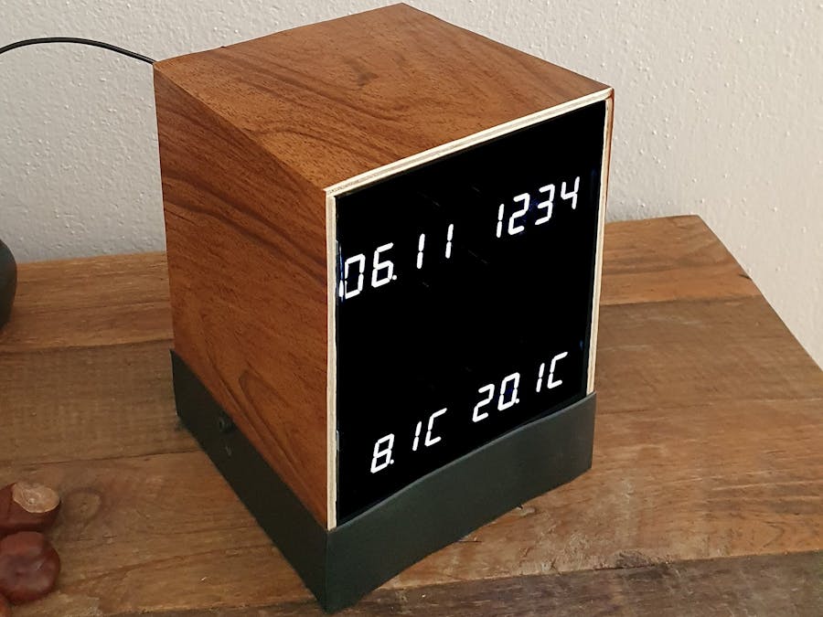
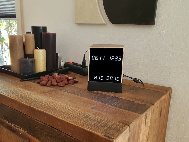
اعتدت أن يكون لدي ساعة رخيصة وغير دقيقة مع عرض درجة الحرارة في غرفة المعيشة الخاصة بنا والتي أردت استبدالها بشيء يمكن ضبط الوقت والتاريخ بنفسها كما تتوقع اليوم. كما يجب أن تعرض بيانات المنزل الذكي Homematic المتوفرة لدي مثل مستشعرات درجة الحرارة وغيرها من المعلومات (مثل مستشعر جرس الباب).
نظرًا لعدم وجود مثل هذا الجهاز في السوق ، قررت أن أصنعه بنفسي.
قررت استخدام Arduino "Mkr Wifi 1010" لهذا المشروع بشكل أساسي لإمكانية الوصول إلى WiFi والموارد المتاحة. كان هناك عدد قليل من التعلم المثيرة للاهتمام والتي أعتقد أنها يمكن أن تكون مفيدة للآخرين بدءًا من نفس اللوحة (انظر الوصف التفصيلي أدناه).
ميزات شاشة HM Clock الخاصة بي:
ساعة دقيقة وذاتية الضبط (تصل إلى خدمة وقت الإنترنت NTP لتعيين RTC للمتحكم الدقيق)
يستقبل ويعرض درجتين من درجات الحرارة (من الداخل والخارج) من Homematic (أو أنظمة المنزل الذكي المماثلة)
يعرض الوقت والتاريخ ودرجات الحرارة على شاشات LED الساطعة المكونة من 7 أقسام
سيتم تعتيم مصابيح LED ذات الأجزاء السبعة في الليل (قابلة للبرمجة)
تعرض شاشة مصفوفة نقطية 8x8 ثنائية اللون رموز الحالة (مثل تحديثات WiFi أو درجة الحرارة أو NTP وما إلى ذلك)
يمكنه عرض معلومات إضافية (على سبيل المثال ، أضفت جرس باب مرئيًا تم تشغيله من مستشعر جرس الباب Homematic)
يمكن التحكم بها عبر صفحة الويب (الوصول إلى شبكة WiFi المحلية باستخدام عنوان IP أو الاسم الرمزي لجهاز التوجيه)
يحتوي على بطارية احتياطية ، ويقيس جهد الإمداد ومستوى البطارية (النسبة المتبقية) ويعرف متى يتم تشغيله بواسطة USB
الأجزاء المستخدمة:
اردوينو MKR Wifi 1010
4x Adafruit 4-Digit 7-Segment Display مع حقيبة ظهر I2C - أبيض ناصع
1x Adafruit Bicolor 8x8 LED Square Pixel Matrix مع حقيبة ظهر I2C
اختياري: LiPo Akku مع موصل JST PHR-2 (3 ، 7 فولت ، 1200 مللي أمبير في الساعة)
تعليمات:
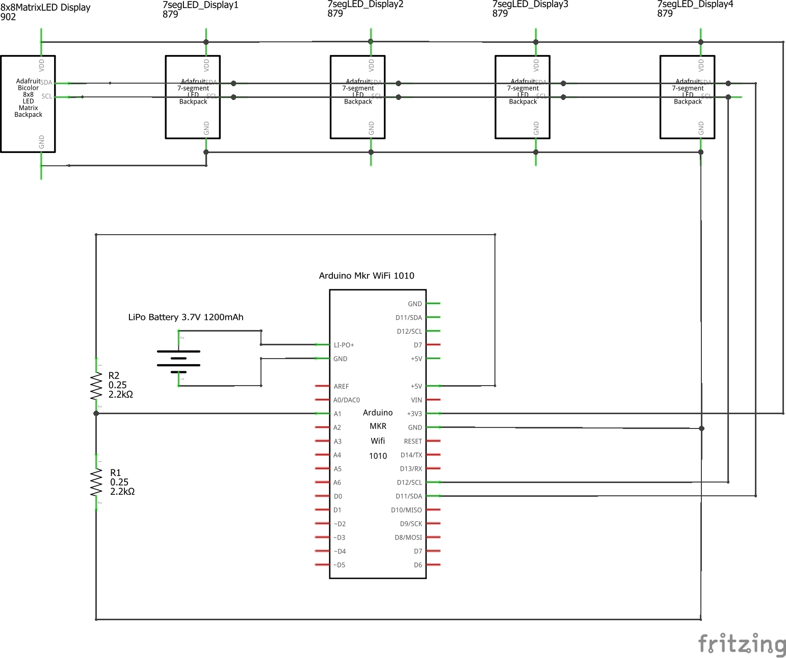
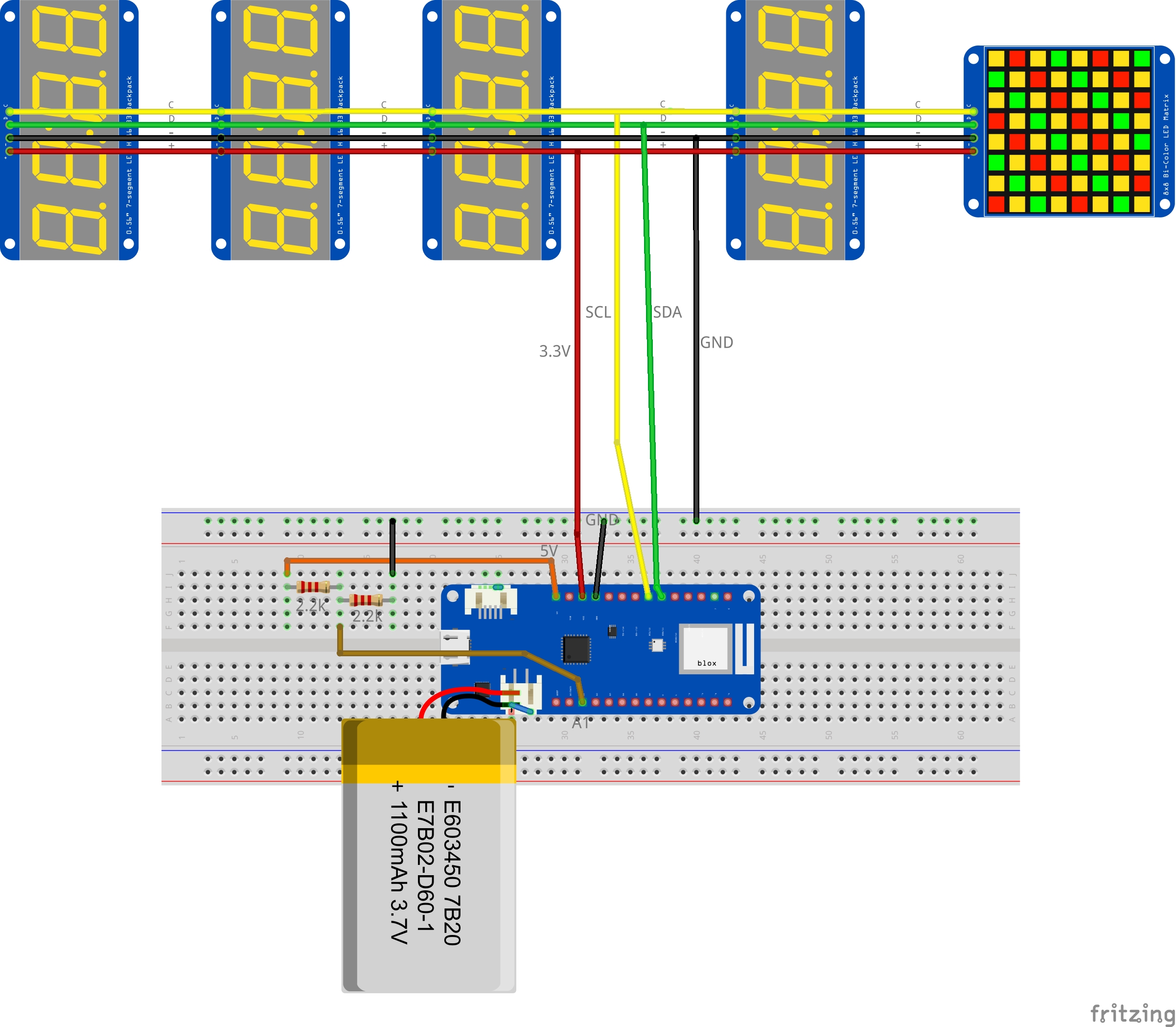
1. لإنشاء ساعة عرض HM الخاصة بك ، أوصي بالبدء على لوح التجارب باستخدام Mkr1010 والشاشات المتصلة بأسلاك التصحيح. (لم يتم تضمين تصميم الصندوق المحيط هنا - ربما سأضيف شيئًا لاحقًا ... ولكن بعد ذلك كنسخة مطبوعة ثلاثية الأبعاد). إعداد الأجهزة سهل حقًا - راجع المخططات المتوفرة:
قم بتركيب لوحة Mkr1010 على لوحة توصيل وتوصيل عبر كبل USB (صغير) بجهاز الكمبيوتر الخاص بك
قم بإعداد وحدات العرض الخمس وتوصيلهم جميعًا بنفس ناقل I2C (دبابيس SCL و SDA لـ Mkr1010) والطاقة (3.3 فولت و GND). تأكد من تعيين عناوين I2C لكل شاشة بشكل صحيح لتجنب العناوين المتضاربة (انظر التفاصيل أدناه)
قم بتوصيل 2 مقاومات متساوية على سبيل المثال 2.2 كيلو بين "5V pin" و "A1" وكذلك بين "A1" و "GND" كمقسم جهد بسيط
قم بتوصيل بطارية LiPo اختياريًا (3.7 فولت ، 1.2 أمبير في الساعة) ؛ تأكد من صحة قطبية الموصل (انظر التفاصيل أدناه) هذا كل شيء.

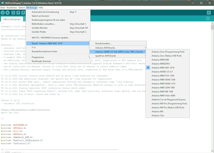
2. قم بإعداد Arduino IDE الخاص بك: 2.1 حدد الهدف أولاً على "اللوحات - لوحات Arduino SAMD - Arduino MKR WiFi 1010" (ربما تريد تجربة بعض أمثلة لوحة Mkr WiFi 1010 البسيطة أولاً)
2.2 ثم قم بتنزيل وتثبيت مكتبات Adafruit-LEDBackpack الضرورية لشاشات العرض التي تعمل بـ I2C (راجع الإرشادات الجيدة المتوفرة على موقع Adafruit على الويب
2.3 احصل على كود مصدر Arduino الخاص بي (انظر أدناه) ، فهو يحتوي على 3 ملفات:
HMClockDisplay.ino - كود المصدر الرئيسي
menu_inline_css7.h - رمز مصدر قائمة HTML (لموقع الويب)
Symbols.h - بعض الرموز لعرض المصفوفة النقطية مقاس 8x8
تأكد من أنها كلها في مجلد واحد
2.4 قم بتغيير إعداداتك الشخصية في قسم "إعدادات المستخدم" في بداية كود المصدر: أدخل SSID لشبكة WiFi المنزلية (الاسم) وكلمة المرور واضبط المنطقة الزمنية والتوقيت الصيفي (DST) حسب الحاجة:
// إعدادات المستخدم: // WIFI Settingschar ssid [] = "XXX" ؛ // اسم شبكة WiFi الخاصة بك [] = "YYY" ؛ // كلمة مرور WiFi الخاصة بك // Timezone Settingsint GMT = 1 ؛ // التكيف مع منطقتك الزمنية (على سبيل المثال ، ألمانيا GMT + 1 -> ضبط على 1) int DST = 0 ؛ // ضبط التوقيت الصيفي (افتراضي = 0: لا DST (التوقيت الشتوي)
ملاحظة: بالنسبة للاختبار المبدئي ، أوصي باستخدام وصول WiFi المحلي "العادي" (لا توجد قيود رئيسية مثل شبكات WLAN الخاصة بالضيف) لتجنب أي مشكلات.
2.5 قم بتجميع الكود وتحميله على لوحة Arduino
استخدم الششة التسلسلية للحصول على معلومات مفصلة من الجهاز للاختبار الأولي. سيكون هناك العديد من مخرجات السجل التي يمكن أن تكون مفيدة لفهم أي مشكلات مثل مشاكل اتصال WiFi وما إلى ذلك.
وصف مفصل:
1. واي فاي نينا
تعتمد لوحة Mkr Wifi 1010 على المتحكم الدقيق SAMD21 المتصل بوحدة من u-blox ، NINA-W10 ، مجموعة شرائح منخفضة الطاقة تعمل في نطاق WiFi 2.4 جيجا هرتز. للوصول إلى شبكة WiFi المحلية الخاصة بك ، توفر مكتبة WiFiNINA المتوفرة جميع الوظائف المطلوبة. هناك الكثير من الأمثلة والمشاريع الحالية التي تستخدم WiFiNina. انظر الوثائق المتاحة على: https://www.arduino.cc/en/Reference/WiFiNINA
في مشروعي ، استخدمت الوصول إلى شبكة WiFi من أجل:

الوصول إلى بروتوكول وقت الإنترنت NTP لضبط ساعة الوقت الفعلي بشكل دوري
توفير صفحة ويب بسيطة للتهيئة (تعمل بشكل أساسي كخادم صغير)
تلقي البيانات من نظام المنزل الذكي Homematic ليتم عرضها (درجات الحرارة وما إلى ذلك)
ملحوظات:
قد تحتاج إلى تحديث برنامج Nina الثابت بعد الإعداد الأولي للوحة Mkr1010 في Arduino IDE. يمكن التحقق من الإصدار وتحديثه في Arudino IDE. تم وصف عملية التحديث هذه في صفحة الويب WiFiNINA المذكورة أعلاه.

للوصول إلى الجهاز من شبكة WiFi المحلية الخاصة بك بسهولة ، قم بتكوين موجه الشبكة الخاص بك لاستخدام نفس عنوان IP له دائمًا. تتيح لك معظم أجهزة التوجيه أيضًا تعيين اسم جهاز (لذلك لا تحتاج إلى كتابة عنوان IP في متصفحك). استخدمت "HMDisplayClock" الذي يتيح لي الوصول إلى صفحة التحكم في أي متصفح داخل شبكة WiFi الخاصة بي عن طريق الكتابة ببساطة
(بدلاً من ذلك ، يعمل أيضًا استخدام عنوان IP الخاص بلوحة Arduino Mkr 1010 بالطبع ...)

إذا كنت ترغب في برمجة جهازك المتصل بشبكة WiFi والذي يحتاج إلى أن يكون متاحًا طوال الوقت ، فإليك نصيحة: تأكد من التحقق بانتظام إذا كنت لا تزال متصلاً أم لا. سيقوم جهاز التوجيه الخاص بك بفصل الأجهزة من الشبكة من وقت لآخر ... لذلك إذا قمت بإنشاء شبكة WiFi مرة واحدة فقط (في روتين الإعداد) ، فستفقد الاتصال بعد بضع ساعات. في حالتي ، أقوم بفحص الاتصال كل ثانية في الروتين الفرعي "handleWifiClient".
2. ساعة الضبط الذاتي
سيحصل Arduino على الوقت المحدد من خدمة بروتوكول وقت الشبكة (NTP) التي ترجع "وقت الحقبة". "الطابع الزمني للعصر" الذي تم إرجاعه هو عدد الثواني التي انقضت منذ 1 يناير 1970. لذلك من الضروري تحويل الطابع الزمني إلى معلومات التاريخ والوقت التي يمكن قراءتها. بالإضافة إلى ذلك ، يجب إجراء تصحيحات المنطقة الزمنية والتوقيت الصيفي. يعتمد الروتين الفرعي لضبط المنطقة الزمنية على العمل الممتاز "حان الوقت" من دوج دومكي (شكرًا للمشاركة!): https://www.hackster.io/doug-domke/self-setting-super-accurate- الساعات 5f1162
لهذا ، كان fixTimeZone () من Doug الروتيني مساعدة كبيرة لأن تعديل المنطقة الزمنية يمكن أن يكون معقدًا إلى حد ما. سيتم ضبط ساعة الوقت الفعلي المدمجة الخاصة بالمتحكم الدقيق (SAMD21) بشكل دوري باستخدام هذه المعلومات (أقوم بالتحديث كل ساعة). بمجرد تلقي تحديث NTP ناجح ، يضيء رمز "NTP" الأخضر لبضع ثوان على شاشة المصفوفة

3. العرض
لتصور جميع المعلومات ، قررت استخدام شاشات LED كبيرة ومشرقة. يمكن تركيبها خلف غطاء زجاجي من الدخان وتسمح بتصميم جميل لوحدة الساعة. بالإضافة إلى ذلك ، أستخدم وحدة مصفوفة ثنائية اللون 8 × 8 لمعلومات الحالة المؤقتة.

جميع وحدات العرض مصنوعة من قبل Adafruit ، وهي موثقة جيدًا وتأتي مع مكتبات برامج. يتم التحكم في شاشات العرض بواسطة I2C (جميعها متصلة بنفس الحافلة) ويمكن تشغيلها بواسطة 3.3 فولت. (لاحظ أن Mkr1010 عبارة عن جهاز 3.3 فولت ، لذلك لا تخلط مع أجزاء 5 فولت!).
عنونة I2C: باستخدام عدة وحدات ، يجب تعيين عناوين I2C لكل وحدة عرض لتجنب العناوين المتضاربة. هناك 3 وصلات لحام لضبط العنوان متوفرة على كل شاشة. تأكد من تعيين عنوان مختلف لكل وحدة ، انظر صفحة Adafruit لمزيد من التفاصيل
في حالتي ، اخترت العناوين التالية (انظر روتين الإعداد): وحدة عرض الوقت: 0x70 وحدة عرض التاريخ: 0x71 Temp1 وحدة العرض: 0x73 Temp2 Display Module: 0x74 Matrix Display Module: 0x72
فحص ميزانية الطاقة: جميع شاشات العرض متصلة بدبوس MKR1010 Board VCC ، وهو خرج منظم 3.3 فولت. تشير مواصفات MKR ZERO إلى أنه يمكنها توفير ما يصل إلى 600 مللي أمبير. هذا هو نفسه بالنسبة إلى MKR WiFi 1010 ، لأنه يستخدم نفس منظم الجهد (AP2112K-3.3). أظهرت قياساتي جميع الشاشات الأربعة التي تم توفيرها بواسطة رسم 3.3 فولت ليس أكثر من 120 مللي أمبير في المجموع ، لذلك يجب أن يكون جيدًا.
4. التكامل Homematic
لتصور المعلومات مثل قيم درجة الحرارة من نظام المنزل الذكي Homematic ، تحتاج الوحدة المركزية (CCUx) إلى توفير بيانات المستشعر للساعة عن طريق اتصال WiFi المحلي. لهذا ، تصل CCU إلى صفحة الويب الخاصة بالساعة بمعامل ... مثل هذا
درجة الحرارة = 20.5 بوصة
باستخدام نسختك الخاصة من الساعة ، حاول إدخال هذا في متصفحك يدويًا أولاً ... إذا نجح كل شيء ، فسيتم تحديث عرض درجة الحرارة المناسبة إلى 20.5 درجة مئوية كما هو موضح أدناه:

ثم اتبع هذه الخطوات لتمكين إرسال البيانات من وحدة التحكم المركزية Homematic (CCUx) إلى الساعة تلقائيًا:
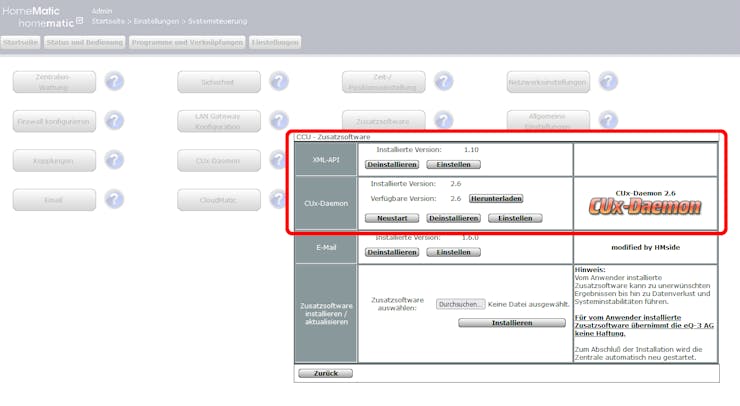
4.1 قم بتثبيت الإضافات التالية في وحدة CCU الخاصة بـ Homematic:
أ) XML-API: يوفر وظيفة طلب xml كواجهة لأجهزة HM المتاحة (مثل أجهزة الاستشعار
ب) CUxD Deamon: لإرسال البيانات باستخدام الأمر النصي CMD_EXEC إلى الساعة باستخدام وصول WiFi
لتمكين وظيفة CMD_EXEC لأول مرة بعد تثبيت CUxD ، أدخل الإعدادات وأنشئ جهازًا جديدًا من النوع "(28) System" مع الوظيفة "Exec" في البرنامج الخفي CUx ، ثم قم بتأكيد الجهاز الجديد عبر صندوق الوارد الخاص بوحدة التحكم المركزية (CCU) وأعد تشغيل CCU (تعليمات هذه الخطوة موجودة هنا (باللغة الألمانية)
4.2 لتحديد أسماء مستشعرات متجانسة معينة (نقاط بيانات) يجب عرضها على HM Display Clock ، اتبع الخطوات التالية: افتح قائمة XML-API:
الإعدادات-> لوحة التحكم -> البرامج الإضافية-> إعدادات XML-API -> قائمة الحالة
.. سيتم سرد جميع المحركات ...
حدد موقع <datapoint> الصحيح وانسخ الاسم الدقيق إلى محرر الرسائل النصية
على سبيل المثال "HmIP-RF.000ED8A9909BB2: 1.ACTUAL_TEMPERATURE"

4.3 قم بإنشاء برنامج CCU بسيط لإرسال البيانات بشكل دوري. في حالتي ، كنت أرغب في إرسال مستشعرات درجة الحرارة الداخلية والخارجية إلى الساعة تلقائيًا كل 10 دقائق

لهذا ، قمت بإنشاء تسلسل يتم التحكم فيه بالوقت كبرنامج CCU كما هو موضح أعلاه. سيتم تنفيذ برنامج CCU هذا كل 10 دقائق ثم يستدعي برنامج نصي مثل هذا:
سلسلة Temp1 = dom.GetObject ("BidCos-RF.OEQ0670990: 1.TEMPERATURE"). القيمة (). ToString (2) ؛ سلسلة Temp2 = dom.GetObject ("HmIP-RF.000ED8A9909BB2: 1.ACTUAL_TEMPERATURE"). القيمة () .ToString (2) ؛ سلسلة url =
tempL = "# Temp1 ؛ dom.GetObject (" CUxD.CUX2801001: 1.CMD_EXEC "). الحالة (" wget -q -O - "#url) ؛ سلسلة url =
tempR = "# Temp2 ؛ dom.GetObject (" CUxD.CUX2801001: 1.CMD_EXEC "). الحالة (" wget -q -O - "#url) ؛
استبدل كائنات المستشعر أعلاه في السطر 1 + 2 بنقاط البيانات التي تختارها (انظر الخطوة 4.2)
(ربما يكون مفيدًا لك أيضًا: لقد استخدمت هذا البرنامج التعليمي المفيد لتعزيز معرفتي الخاصة بهذا الموضوع (باللغة الألمانية):
يمكن تمديد الطريقة المذكورة أعلاه إلى أبعد من ذلك بالطبع. في حالتي ، استخدمتها أيضًا لإظهار رمز جرس الباب في كل مرة يتم فيها تنشيط مستشعر جرس الباب.

أخيرًا - فقط للاكتمال - بدلاً من Homematic ، يمكنك بالطبع استخدام أي خدمة محلية أخرى لتوفير البيانات ، طالما يمكنك إرسال المعلومات بتنسيق الوصول http الموضح أعلاه.
5. البطارية (اختياري)
يمكنك استخدام بطارية Li-Po القابلة لإعادة الشحن للحفاظ على تشغيل ساعتك بعد فصل طاقة USB كخيار. تحتوي لوحة Arduino Mkr WiFi 1010 على دائرة شحن Li-Po مدمجة للشاحن (BQ24195) والتي تسمح لـ Arduino MKR WiFi 1010 بالعمل على طاقة البطارية أو مصدر خارجي 5 فولت ، وشحن بطارية Li-Po أثناء التشغيل على طاقة خارجية .
لاكتشاف USB-Power (+ Charging) أو وضع البطارية في التطبيق ، فإن قياس دبوس الإخراج "5V" للوحة Mkr1010 هو طريقة مناسبة: إذا كان الجهد المقاس على دبوس 5V حوالي 5 فولت ، فسيتم توصيل طاقة USB إذا كانت البطارية 3.3 فولت ، استخدم مقسم جهد 2: 1 (2xR) من دبوس 5 فولت إلى A1 و GND لمراقبة مستوى الجهد (حيث لا يمكن توفير 5 فولت لمدخلات ADC 3.3 فولت!). تفاصيل.
لقياس جهد البطارية نفسه ، استخدم إشارة الإدخال المتوفرة على لوحة Mkr1010 بواسطة "sensorValue = analogRead (ADC_BATTERY)؛"
يعتب الجهد الكهربائي (3.3-4.2 فولت) مؤشرًا جيدًا على السعة المتبقية. أقوم بتقييم 5 مستويات مختلفة (انظر التعليمات البرمجية المصدر).
ملحوظات :
استخدام بطارية Li-Po أحادية الخلية قابلة لإعادة الشحن ، 3.7 فولت ، حوالي 1024 مللي أمبير في الساعة موصى بها من قبل Arduino
نوع الموصل للبطارية هو JST PHR-2 (على جانب Arduino هو JST S2B-PH-SM4-TB). هام: تحقق من قطبية موصل JST PHR-2! مع وجود موصل USB للوحة على يسارك ، يجب أن يكون + هو الدبوس الأيسر (الموجه نحو موصل USB) ، انظر الصورة أدناه. بعض بطاريات LiPo المتاحة لها قطبية عكسية ! لحسن الحظ ، من السهل تغيير قطبية الموصل إذا لزم الأمر

ملاحظة مهمة حول تبديل مصادر الطاقة - هذا غير موثق جيدًا: وفقًا لـ Arduino ، يجب أن يتم التبديل من مصدر طاقة إلى آخر تلقائيًا. ولكن: إذا كان MKR Wifi 1010 يعمل على بطارية Li-Po ثم يتم توصيل USB للشحن ، سيكون التيار محدودًا بشكل كبير ، ونتيجة لذلك ، سوف يومض CRG LED بعد فترة وسيتم إيقاف تشغيل اللوحة بسبب عدم كفاية الطاقة. ويرجع ذلك إلى القيود التالية: نظرًا لعدم تنفيذ وظيفة مراقبة USB (D + و D-) لشريحة TI BQ ، فإنها غير قادرة على تحديد نوع مصدر الطاقة. ونتيجة لذلك ، يكتب BQ24195L خزنة قيمة 0x30 في reg 0x00 مما يحد من طاقة الإدخال إلى 100mA. ثم يدخل الشحن في وضع DPM وينخفض جهد الشحن على البطارية للحد من التيار. (مصدر
الحل: هناك حاجة إلى إعادة الضبط إذا تم التبديل من البطارية مرة أخرى إلى طاقة USB للعودة إلى الإعدادات الافتراضية ، وفي حالتي ، أستخدم إعادة تعيين المراقبة (انظر كود المصدر). على سبيل المثال إعادة تكوين BQ24195) ، ولكن بالنسبة لي كان هذا كافياً
Homematic Display Clock كود المصدر الرئيسي
/* Homematic Clock Display ======================= An interactive clock display for Homematic with WiFi Control Based on the Arduino MKR WiFi 1010 Board Features : - accurate, self-setting clock (accesses NTP internet time service to set the RTC of the microcontroller) - receives and displays 2 temperatures (inside and outside) from Homematic (or similar smart-home systems) - displays time, date and temperatures on bright 7-segment-LED displays - 7-segment LEDs will be dimmed at night time (programmable) - an additional 8x8 bicolor dot-matrix display shows status symbols (e.g. WiFi, Temperature or NTP updates etc) - can display additional information (e.g. I added a visual door-bell triggered from my Homematic door-bell sensor) - can be controlled via Webpage (access in local WiFi using the IP address or router symbolic name) - has a backup battery, measures supply voltage and battery level (remaining %) and knows when it's USB-powered V1 16.10.2021 initial version with 16x2LCD and 2x white 7-seg displays for time&date V2 23.10.2021 add additional displays: 8x8 matrix and 2x 7-seg displays for temperature V3 24.10.2021 better HTML menu , remote temperature setting and changed to different temp 7-seg displays V4 01.11.2021 Watchdog implemented : need to reset after USB-repowering (BQ24195 charger IC goes in safe mode=current limited!) V5 04.11.2021 Startup improved, WiFi connection status check added V6 13.11.2021 fixed "WiFi repeating effect", deleted LCD, swap 7seg positions, different reset method, add log buffer V7 05.12.2021 fix of minor issues and brush up future to do's: - automatic DST correction https://www.hackster.io/mac70/projects mac70 Dec 2021 */ #include <WiFiNINA.h> #include <RTCZero.h> #include <Wire.h> #include <WDTZero.h> #include <Adafruit_GFX.h> #include "Adafruit_LEDBackpack.h" #include "LedControl.h" // ----------------------------------------------------------------------------------------- // USER settings : // WIFI Settings char ssid[] = "XXX"; // your WiFi network name char pass[] = "YYY"; // your WiFi password // Timezone Settings int GMT = 1; // adapt to your time zone (e.g. Germany is GMT+1 -> set to 1 ) int DST = 0; // adjust daylight saving time (default = 0 : no DST (Wintertime),... // ...from 31-March thru 31-Oct -> set to +1) // ----------------------------------------------------------------------------------------- const String Version = "1.7"; // Version of this module // some instances RTCZero rtc; // create instance of real time clock WiFiServer server(80); // create server instance WDTZero MyWatchDoggy; // create WDT for reset // Define all displays : Adafruit_7segment Time7SegDis = Adafruit_7segment(); // 7 seg display for Time Display Adafruit_7segment Date7SegDis = Adafruit_7segment(); // 7 seg display for Date Display Adafruit_7segment TempL7SegDis = Adafruit_7segment(); // 7 seg display for Temp Display Adafruit_7segment TempR7SegDis = Adafruit_7segment(); // 7 seg display for Temp Display Adafruit_BicolorMatrix matrix = Adafruit_BicolorMatrix(); // 8x8 dot matrix display // Variables // status variables int status = WL_IDLE_STATUS; // WiFi connection status unsigned long lastepochrec=0; // last successful update of Epoc record unsigned long lastNTPupdate=0; // last update time received from NTP unsigned long tempupdaterec=0; // last successful temp update time unsigned long starttime; // holds millis() value in setup routine // display controls int brightness=14; // 7seg LED normal display brightness (0..15) int dim_brightness=4; // 7seg LED reduced brightness level (for night time display) int dimstart=21; // dimming of LEDs period start... int dimend=6; // ...end time (h) boolean drawDots = false; // show dots on 7 seg display boolean drawCol = false; // show colon on 7 seg display int ledpin=6; // LED connected to pin 6 bool led1=false; // LED status int showdotmatrix=-1; // indicates if something should be displayed on dot matrix // date and time int myhours, mins, secs; // current time int myday, mymonth, myyear; // current date int myClock = 24; // default is 24h (can be 12 alternativly, untested) int dateOrder = 0; // date format default is 0=DMY (can be set to 1=MDY, untested) bool IsPM = false; // only used in case of 12h clock String resetTime; // holds inital time&date after last reset in readable format String currenttime,currentdate; // holds current time&date in readable format // temperatures float temp_in=-99.0; // temperature value for inside ... float temp_out=-99.0; // ... and outside (invalid if -99) // log buffer const unsigned int logsize=50; // number of lines in log buffer (can be adjusted if needed) String loglines[logsize]; // buffer array for loglines unsigned int logpointer=0; // write-pointer to next line in logbuffer signed int logstart=-logsize; // read-pointer for complete buffer readout // battery and ext voltage monitoring int sensorValue; // direct ADC channel for Bat float voltage; // converted reading into real voltage float batlevel; // batlevel as remaining capacity 0...100% float batbars; // batlevel as "5 bar" battery symbol float power5; // status of 5V pin (shows "on bat" or "on ext power") boolean onbattery=false; // indicates if no external power is connected // some simple 8x8 bitmaps for the matrix display (stored in the following "include" file :) #include "symbols.h" /* -------------------------------------------------------------------------------------- Setup after Reset -------------------------------------------------------------------------------------- */ void setup() { starttime=millis(); addlogentry("Start after reset t="+String(millis()-starttime, DEC)); // init IOs analogReadResolution(12); // set ADC resolution (4096) pinMode(ledpin, OUTPUT); // for built-in LED // init UART0 for serial monitor Serial.begin(9600); //Initialize serial port // Init Time&Date 7seg displays (on I2C bus) Time7SegDis.begin(0x70); // 3 Address Select pins: 0x70 thru 0x77 Time7SegDis.setBrightness(brightness); // 0..15 Time7SegDis.blinkRate(3); // 0 is no blinking. 1, 2 or 3 is for display blinking Time7SegDis.print(88.88); // show "88:88" initially Time7SegDis.writeDisplay(); Date7SegDis.begin(0x71); // 3 Address Select pins: 0x70 thru 0x77 Date7SegDis.setBrightness(brightness); // 0..15 Date7SegDis.blinkRate(3); // 0 is no blinking. 1, 2 or 3 is for display blinking Date7SegDis.print(88.88); // show "88:88" initially Date7SegDis.writeDisplay(); // Init Temperature 7 seg display setup (on I2C bus) TempL7SegDis.begin(0x74); // 3 Address Select pins: 0x70 thru 0x77 TempL7SegDis.setBrightness(brightness); // 0..15 TempL7SegDis.blinkRate(0); // 0 is no blinking. 1, 2 or 3 is for display blinking TempL7SegDis.drawColon(false); // no ":" will be shown TempL7SegDis.writeDigitRaw(0, 0b01000000); // display "---C" initially TempL7SegDis.writeDigitRaw(1, 0b01000000); TempL7SegDis.writeDigitRaw(3, 0b01000000); TempL7SegDis.writeDigitNum(4, 0xC, false); TempL7SegDis.writeDisplay(); // update display TempR7SegDis.begin(0x73); // 3 Address Select pins: 0x70 thru 0x77 TempR7SegDis.setBrightness(brightness); // 0..15 TempR7SegDis.blinkRate(0); // 0 is no blinking. 1, 2 or 3 is for display blinking TempR7SegDis.drawColon(false); // no ":" will be shown TempR7SegDis.writeDigitRaw(0, 0b01000000); // display "---C" initially TempR7SegDis.writeDigitRaw(1, 0b01000000); TempR7SegDis.writeDigitRaw(3, 0b01000000); TempR7SegDis.writeDigitNum(4, 0xC, false); TempR7SegDis.writeDisplay(); // update display // Init 8x8 Dot Matrix Display matrix.begin(0x72); // I2C address of display matrix.setBrightness(15); matrix.blinkRate(0); matrix.setRotation(3); // set rotation orientation of display - here : pin connectors are top matrix.clear(); matrix.drawPixel(0, 0, LED_RED); // show one pixel matrix.writeDisplay(); // write the changes we just made to the display // first UART message int t = 10; //wait for serial port to open, max 5 seconds while (!Serial) { delay(500); if ( (t--) == 0 ) break; } Serial.print("\nHomematic Display Clock\n"); Serial.println("======================="); Serial.print("Version ="); Serial.println(Version); // check if there is the WiFi module accessable if (WiFi.status() == WL_NO_MODULE) { Serial.println("Fatal Error : Communication with WiFi module failed! - Abort...!!"); addlogentry("Fatal Error : Communication with WiFi module failed!"); matrix.print("E"); matrix.writeDisplay(); matrix.blinkRate(1); // don't continue while (true); } Serial.println("Found WiFi module."); String fv = WiFi.firmwareVersion(); if (fv < WIFI_FIRMWARE_LATEST_VERSION) { Serial.println("Warning : Please upgrade the WiFi module firmware !"); addlogentry("Warning : Please upgrade the WiFi module firmware !"); } else { Serial.println("WiFi module Firmware OK."); addlogentry("WiFi module Firmware OK"); } // print your MAC address: byte mac[6]; WiFi.macAddress(mac); Serial.print("MAC: "); printMacAddress(mac); // show a blinking red WiFi Symbol matrix.clear(); matrix.drawBitmap(0, 0, WiFi_bmp, 8, 8, LED_RED); matrix.blinkRate(1); matrix.writeDisplay(); // Begin WiFi Serial.println("Scanning available networks..."); int numSsid = WiFi.scanNetworks(); if (numSsid == -1) // Fatal Error: Couldn't get a WiFi connection { Serial.println("WiFi ERROR..."); matrix.blinkRate(3); // fast blinking WiFi symbol matrix.writeDisplay(); while (true); // application will hang... } // print the list of networks found: Serial.print("number of available networks:"); Serial.println(numSsid); if (numSsid == 0) // no WiFi networks found { Serial.println("!! No WiFi Networks found ... change position of device for better reception !!"); // show a fast blinking red WiFi Symbol matrix.clear(); matrix.drawBitmap(0, 0, WiFi_bmp, 8, 8, LED_RED); matrix.blinkRate(3); matrix.writeDisplay(); delay(1000); } else // WiFi networks found { matrix.blinkRate(0); matrix.writeDisplay(); } // print the network number and name for each network found: for (int thisNet = 0; thisNet < numSsid; thisNet++) { Serial.print(thisNet); Serial.print(") "); Serial.print(WiFi.SSID(thisNet)); Serial.print("\tSignal: "); Serial.print(WiFi.RSSI(thisNet)); Serial.println(" dBm"); } // connect to WiFi network int attempts=0; Serial.println("Try to connect to WiFi..."); while (status != WL_CONNECTED) // as we need WiFi, keep trying until WiFi is connected... { if (status != WL_CONNECTED) { delay(250); matrix.drawPixel(7, 7, 0); // indicate connection attempts by flashing pixel matrix.writeDisplay(); } Serial.print(attempts); Serial.print(" attempts to connect to SSID: "); Serial.print(ssid); // Connect to WPA/WPA2 network. Change this line if using open or WEP network: status = WiFi.begin(ssid, pass); // print the received signal strength: long rssi = WiFi.RSSI(); Serial.print(" - signal strength (RSSI):"); Serial.print(rssi); Serial.println(" dBm"); attempts++; delay(250); matrix.drawPixel(7, 7, LED_RED); matrix.writeDisplay(); } // WiFi connected, show a green WiFi Symbol matrix.clear(); matrix.drawBitmap(0, 0, WiFi_bmp, 8, 8, LED_GREEN); matrix.writeDisplay(); Serial.println("Connected to WiFi."); addlogentry("Connected to WiFi t="+String(millis()-starttime, DEC)); delay(250); // Try to connect to NTP and get time intially Serial.println("trying to get NTP time..."); addlogentry("trying to get NTP time..."); WiFi.setDNS(IPAddress(8, 8, 8, 8)); rtc.begin(); // show a Red NTP Symbol matrix.clear(); matrix.drawBitmap(0, 0, NTP_bmp, 8, 8, LED_RED); matrix.writeDisplay(); // get Epoch time from Internet Time Service and set RTC setRTC(); fixTimeZone(); // NTP received, show a green NTP Symbol matrix.clear(); matrix.blinkRate(0); matrix.drawBitmap(0, 0, NTP_bmp, 8, 8, LED_GREEN); matrix.writeDisplay(); showdotmatrix=8; // output initial time Serial.println("\nInitial Time after Reset : "); print2digitsSer(myhours); Serial.print(":"); print2digitsSer(mins); Serial.print(":"); print2digitsSer(secs); Serial.print(" "); Serial.print(myday); Serial.print("."); Serial.print(mymonth); Serial.print(" "); resetTime = String(myday)+"."+String(mymonth)+" "+String(myhours)+":"+String(mins); addlogentry("Reset Time= "+resetTime); // start to act as Internet Server to enable the HTML menu server.begin(); // end of setup routine Time7SegDis.blinkRate(0); // stop blinking Date7SegDis.blinkRate(0); Serial.print("Setup completed t="+String(millis()-starttime, DEC)); addlogentry("Setup completed t="+String(millis()-starttime, DEC)); addlogentry("Start normal operation..."); } /* -------------------------------------------------------------------------------------- Main Loop -------------------------------------------------------------------------------------- */ void loop() { secs = rtc.getSeconds(); // get current time from real time clock if (secs == 0) fixTimeZone(); // each minute at 0s, correct time zone showTime(); // Display time and date showTemp(); // Display temperatures show_battery_status(); // Detect Supply voltage and get battery level showMatrixDisplay(); // Display Symbols on 8x8 dot matrix display (if required) adjustDimming(); // adjust 7seg LED brightness depending on time handleWifiClient(); // handle WiFi clients (browser for HTML Menu etc) // wait for next second ... while (secs == rtc.getSeconds())delay(10); // wait until seconds change if (mins==59 && secs ==0) setRTC(); // get NTP time every hour at minute 59 and update RTC } /* -------------------------------------------------------------------------------------- Display/Output current Time -------------------------------------------------------------------------------------- */ void showTime() { // UART0 output if (secs==0) // print full time&date, temp and and battery stats each minute at 0 secs { Serial.println(); print2digitsSer(myhours); Serial.print(":"); print2digitsSer(mins); Serial.print(":"); print2digitsSer(secs); if (myClock==12) { if(IsPM) Serial.print(" PM"); else Serial.print(" AM"); } Serial.print(" "); Serial.print(myday); Serial.print("."); Serial.print(mymonth); Serial.print(" TempI="); Serial.print(temp_in); Serial.print(" TempO="); Serial.print(temp_out); if (onbattery) { Serial.print(" on battery (Bat="); Serial.print(batlevel); Serial.print("% ="); Serial.print(voltage); Serial.print("V) |"); } else Serial.print(" USB powered |"); } else // for each second print "." { if ((secs==10) || (secs==20) || (secs==40) || (secs==50)) Serial.print("*"); else if ((secs==30) || (secs==59)) Serial.print("|"); else Serial.print("."); currenttime=String(myhours)+":"+String(mins)+":"+String(secs); currentdate=String(myday)+"."+String(mymonth); } //7-seg display Time output Time7SegDis.writeDigitNum(0, (myhours / 10) % 10, drawDots); Time7SegDis.writeDigitNum(1, myhours % 10, drawDots); Time7SegDis.drawColon(drawCol); Time7SegDis.writeDigitNum(3, (mins / 10) % 10, drawDots); Time7SegDis.writeDigitNum(4, (mins % 10), drawDots); Time7SegDis.writeDisplay(); drawCol=!drawCol; //7-seg display Date output Date7SegDis.writeDigitNum(0, (myday / 10) % 10, false); Date7SegDis.writeDigitNum(1, myday % 10, true); Date7SegDis.drawColon(false); Date7SegDis.writeDigitNum(3, (mymonth / 10) % 10, false); Date7SegDis.writeDigitNum(4, (mymonth % 10), false); Date7SegDis.writeDisplay(); } /* -------------------------------------------------------------------------------------- Display/Output Temperature on 7seg LEDs -------------------------------------------------------------------------------------- */ void showTemp() { if (temp_in > -99.0) { displayTempL(temp_in); // display on left display } if (temp_out > -99.0) { displayTempR(temp_out); // display on right display } } /* -------------------------------------------------------------------------------------- get exact time from Internet Time Service (NTP) and set the RTC module to this time -------------------------------------------------------------------------------------- */ void setRTC() { unsigned long epoch; int numberOfTries = 0, maxTries = 15; // try to access NTP service until successful do { do { numberOfTries++; epoch = WiFi.getTime(); // Try to get NTP time if (epoch == 0) delay(500); // failed, wait until next try else { lastNTPupdate=epoch; // success, remember last update time lastepochrec = millis()-starttime; } } while ((epoch == 0) && (numberOfTries < maxTries)); // repeat a number of times if (numberOfTries == maxTries) // not successful { Serial.print(currenttime+" "+currentdate+" could not reach NTP"); addlogentry(currenttime+" "+currentdate+" could not reach NTP"); // show a Red blining NTP Symbol matrix.clear(); matrix.drawBitmap(0, 0, NTP_bmp, 8, 8, LED_RED); matrix.blinkRate(2); matrix.writeDisplay(); } else // success { rtc.setEpoch(epoch); Serial.print(currenttime+" "+currentdate+" NTP update successful. Epoch= "); Serial.println(epoch); addlogentry(currenttime+" "+currentdate+" NTP update successful. Epoch="+String(epoch)); // show a green NTP Symbol for a few seconds matrix.clear(); matrix.blinkRate(0); matrix.drawBitmap(0, 0, NTP_bmp, 8, 8, LED_GREEN); matrix.writeDisplay(); showdotmatrix=8; if (onbattery) addlogentry("Currently running on battery. Remaining="+String(batlevel)+"%"); // add a note here if on bat } } while (lastNTPupdate==0); // repeat again and again if no NTP access was achieved yet (endless loop only can happen at start-up) } /* -------------------------------------------------------------------------------------- Adjust 7seg LED Brightness depending on time -------------------------------------------------------------------------------------- */ void adjustDimming() { if (mins==0 && secs==0 && myhours==dimstart) // if start-time of dimming has been reached { Time7SegDis.setBrightness(dim_brightness); // set to reduce brightness Date7SegDis.setBrightness(dim_brightness); TempL7SegDis.setBrightness(dim_brightness); TempR7SegDis.setBrightness(dim_brightness); Serial.print("brightness level dimmed"); addlogentry("brightness level dimmed"); } if (mins==0 && secs==0 && myhours==dimend) // if end-time of dimming has been reached { Time7SegDis.setBrightness(brightness); // set brightness back to normal level Date7SegDis.setBrightness(brightness); TempL7SegDis.setBrightness(brightness); TempR7SegDis.setBrightness(brightness); Serial.print("brightness level set to normal"); addlogentry("brightness level set to normal"); } } /* -------------------------------------------------------------------------------------- Show Dot Matrix Symbols for a few seconds if required -------------------------------------------------------------------------------------- */ void showMatrixDisplay() { if (showdotmatrix > 0) { matrix.setBrightness(showdotmatrix); // adjust brightness of showing symbol on dotmatrix showdotmatrix--; // decrease seconds to show if (showdotmatrix==0) // if zero, clear matrix display again { matrix.clear(); matrix.writeDisplay(); matrix.setBrightness(15); showdotmatrix=-1; } } else if (showdotmatrix==-1 && onbattery) show_batbars(batbars); // else show battery bar display if on battery } /* -------------------------------------------------------------------------------------- // listen for incoming Wifi clients and process WiFi commands -------------------------------------------------------------------------------------- */ void handleWifiClient() { String currentLine = ""; // a String to hold incoming data from the client String commandLine = ""; // holds additional commands (after "?") String cmdpar = ""; int clientcmd; // position of "?" int len; boolean cmdproc = false; // indicates if a command was executed with this current client alreday String lastepochrec2, tempupdaterec2; // first check if still connected with WiFi network if (WiFi.status() != WL_CONNECTED) // if no longer connected... { // ...show a red WiFi Symbol ... matrix.clear(); matrix.drawBitmap(0, 0, WiFi_bmp, 8, 8, LED_RED); matrix.writeDisplay(); showdotmatrix=5; // ... and (re-)connect to network. WiFi.disconnect(); status = WiFi.begin(ssid, pass); Serial.println(currenttime+" re-connecting to WiFi..."); addlogentry(currenttime+" re-connecting to WiFi "); } else // if still connected to WiFi { // start server mode WiFiClient client = server.available(); cmdproc=false; if (client) // if an outside client request was received (from a browser etc) { boolean currentLineIsBlank = true; currentLine = ""; while (client.connected()) // as long as client is connected { if (client.available()) // and available { // prepare variables to show on HTML page IPAddress ip = WiFi.localIP(); unsigned int ler_min = ((millis() - lastepochrec)/60000); unsigned int ler_sec = ((millis() - lastepochrec)/1000) - (ler_min*60); lastepochrec2 = String(ler_min)+":"+String(ler_sec); // contains how long ago the last NTP update was if (tempupdaterec!=0) { unsigned int ltr_min = ((millis() - tempupdaterec)/60000); unsigned int ltr_sec = ((millis() - tempupdaterec)/1000) - (ltr_min*60); tempupdaterec2 = String(ltr_min)+":"+String(ltr_sec); // contains how long ago the last temperture update was } else tempupdaterec2 = "never"; int ll=logstart; // for the log buffer dump if (ll<0) ll=0; int li=0; // parse client message char c = client.read(); if (c == '\n' && currentLineIsBlank) // repond to client after CR { // first send a standard HTTP response header client.println("HTTP/1.1 200 OK"); client.println("Content-Type: text/html"); client.println("Connection: close"); // the connection will be closed after completion of the response // client.println("Refresh: 5"); // refresh the page automatically every 5 sec client.println(); // send entire HTML code for device website // HTML (converted to C outputs) is located in external file : #include "menu_inline_css7.h" break; } if (c == '\n') { // starting a new line // Serial.println("WiFi Client request="+currentLine); // for debugging : print each request line from client currentLineIsBlank = true; currentLine = ""; } else if (c != '\r') { // received a character on the current line currentLineIsBlank = false; currentLine += c; // add it to the end of the currentLine } // process received WiFi commands : if ((c == '\r') && (cmdproc==false)) // if CR, look for additional commands received, if no already done (otherwise just a request to display the menu) { clientcmd = currentLine.indexOf('?'); // position of "?" in the request line ("?" indicates a command) if (clientcmd>0) // if a command have been detected { // extract command out of received line len=currentLine.length(); commandLine = currentLine.substring(clientcmd+1,len); // extract string from "?".. commandLine = commandLine.substring(0,commandLine.indexOf(' ')); // ..until first SPACE // output command on UART Serial.print("\nWiFi Command "); Serial.print(commandLine); // command handling : if (commandLine.endsWith("ibr")) // adjust 7seg LED display brightness { Serial.println(" --> Inc LED backlight"); if (brightness<14) brightness++; Time7SegDis.setBrightness(brightness); Date7SegDis.setBrightness(brightness); TempL7SegDis.setBrightness(brightness); TempR7SegDis.setBrightness(brightness); cmdproc=true; } if (commandLine.endsWith("dbr")) { Serial.println(" --> Dec LED backlight"); if (brightness>0) brightness--; Time7SegDis.setBrightness(brightness); Date7SegDis.setBrightness(brightness); TempL7SegDis.setBrightness(brightness); TempR7SegDis.setBrightness(brightness); cmdproc=true; } if (commandLine.endsWith("idims")) // adjust auto reduced brightness dimming time start and end times { Serial.println(" --> Inc dim time start"); dimstart++; cmdproc=true; } if (commandLine.endsWith("ddims")) { Serial.println(" --> Dec dim time start"); dimstart--; cmdproc=true; } if (commandLine.endsWith("idime")) { Serial.println(" --> Inc dim time end"); dimend++; cmdproc=true; } if (commandLine.endsWith("ddime")) { Serial.println(" --> Dec dim time end"); dimend--; cmdproc=true; } if (commandLine.startsWith("tempL=")) // set value on left temp display { cmdpar = commandLine.substring(6, commandLine.length()); Serial.print(" --> set L temperature to "); Serial.println(cmdpar); temp_in=cmdpar.toFloat(); // show a green Temp Symbol for a few seconds matrix.clear(); matrix.blinkRate(0); matrix.drawBitmap(0, 0, temp_bmp, 8, 8, LED_GREEN); matrix.writeDisplay(); showdotmatrix=5; tempupdaterec = millis()-starttime; cmdproc=true; } if (commandLine.startsWith("tempR=")) // set value on right temp display { cmdpar = commandLine.substring(6, commandLine.length()); Serial.print(" --> set R temperature to "); Serial.println(cmdpar); temp_out=cmdpar.toFloat(); // show a green Temp Symbol for a few seconds matrix.clear(); matrix.blinkRate(0); matrix.drawBitmap(0, 0, temp_bmp, 8, 8, LED_GREEN); matrix.writeDisplay(); showdotmatrix=5; tempupdaterec = millis()-starttime; cmdproc=true; } if (commandLine.startsWith("mxteston")) // display a bell picture on matrix display for some seconds { // show a Symbol for a few seconds matrix.clear(); matrix.blinkRate(0); matrix.drawBitmap(0, 0, bell_bmp, 8, 8, LED_RED); matrix.writeDisplay(); showdotmatrix=10; cmdproc=true; } if (commandLine.endsWith("ledon")) // mostly for testing only : toggle built-in LED { Serial.println(" --> Built-in LED ON"); led1=true; digitalWrite(ledpin,HIGH); cmdproc=true; } if (commandLine.endsWith("ledoff")) { Serial.println(" --> Built-in LED OFF"); led1=false; digitalWrite(ledpin,LOW); cmdproc=true; } } } } } delay(1); // give the web browser time to receive the data client.stop(); // close the connection } } } /* -------------------------------------------------------------------------------------- Fix Time Zone (adds GMT and DST and does all necessary corrections) -------------------------------------------------------------------------------------- */ void fixTimeZone() { int daysMon[13] = {0, 31, 28, 31, 30, 31, 30, 31, 31, 30, 31, 30, 31}; if (myyear % 4 == 0) daysMon[2] = 29; // fix for leap year // get current time from real time clock module myhours = rtc.getHours(); mins = rtc.getMinutes(); myday = rtc.getDay(); mymonth = rtc.getMonth(); myyear = rtc.getYear(); myhours += GMT; // adjust time zone myhours += DST; // and correct DST // To do : Auto DST corrections add later here ... // ... // do corrections in case necessary : if (myhours < 0) // if hours rolls negative { myhours += 24; // keep in range of 0-23 myday--; // fix the day if (myday < 1) // fix the month if necessary { mymonth--; if (mymonth == 0) mymonth = 12; myday = daysMon[mymonth]; if (mymonth == 12) myyear--; // fix the year if necessary } } if (myhours > 23) // if hours rolls over 23 { myhours -= 24; // keep in range of 0-23 myday++; // fix the day if (myday > daysMon[mymonth]) // fix the month if necessary { mymonth++; if (mymonth > 12) mymonth = 1; myday = 1; if (mymonth == 1)myyear++; // fix the year if necessary } } if (myClock == 12) // this is for 12 hour clock { IsPM = false; if (myhours > 11)IsPM = true; myhours = myhours % 12; // convert to 12 hour clock if (myhours == 0) myhours = 12; // show noon or midnight as 12 } } /* -------------------------------------------------------------------------------------- // measure and display external voltage supply condition -------------------------------------------------------------------------------------- */ void show_battery_status() { // Get Battery Level (available on Mkr1010 board) sensorValue = analogRead(ADC_BATTERY); // Convert the analog reading (which goes from 0 - 4095) to a real voltage (0 - 4.208V): voltage = sensorValue * (4.208 / 4095.000); // (0-4.208V) batlevel = 100*(voltage-3.3)/0.8; // calc bat level in % if (batlevel < 0) batlevel=0; // if no battery connected if (batlevel > 100) batlevel=100; // if charging // determine "bars" for battery gauge if (voltage < 3.4) batbars =0; else if (voltage>=3.4 && voltage<3.46) batbars = 1; else if (voltage>=3.46 && voltage<3.62) batbars = 2; else if (voltage>=3.62 && voltage<3.78) batbars = 3; else if (voltage>=3.78 && voltage<3.94) batbars = 4; else if (voltage>=3.94) batbars = 5; // Detect USB-Power (Charging) or Battery Mode by measuring the 5V output pin of the Mkr1010 // use 2:1 voltage divider (2xR) on 5V pin to A1 and GND to monitor voltage level power5 = analogRead(A1) * (3.3 / 4095.000); // USB(5V)>=2.5V ; Bat(3.3V)<=1.6V // detect USB Power (Charge) or Battery Mode if (power5 > 2.2) // ext.power,charging { if (onbattery) // switched from battery to USB -> need to RESET the board to fix the following behaviour : // if you have an arduino mkr wifi 1010 connected to a li-po battery and plug it in to charge // but do not reset the arduino it will be dramatically current limited (100mA charge only), leading to an error after some time // the red charge LED will flash and the device will not work properly anymore, so we need a RESET { MyWatchDoggy.setup(WDT_HARDCYCLE4S); // initialize hardware watchdog after 4S if not cleared before // show a blinking reset Symbol matrix.clear(); matrix.drawBitmap(0, 0, reset_bmp, 8, 8, LED_RED); matrix.blinkRate(2); matrix.writeDisplay(); delay(1000); Serial.println(currenttime+" Watchdog reset in 4 sec - wait for reset \n"); addlogentry(currenttime+" Switch from bat to USB power -> will RESET in 4 sec... "); for (int t = 1; t > 0; ++t) { Serial.print(t);Serial.print("."); delay(950); } } } else // on backup battery { if (onbattery==false) // if just switched from USB power to battery, output message { Serial.println(currenttime+" Swichted to Battery Supply! Remaining="+String(batlevel)+"%"); addlogentry(currenttime+" Swichted to Battery Supply! Remaining="+String(batlevel)+"%"); } onbattery=true; // remember status "on battery" (also for next time it changes to USB power ...needs a reset then) } } /* -------------------------------------------------------------------------------------- // display battery status as bar symbol -------------------------------------------------------------------------------------- */ void show_batbars(int bar) { // draw the battery status using 5 bars (green and red) for (int i=1; i<=bar; i++) { matrix.drawLine(2,7-i, 5,7-i, LED_GREEN); matrix.writeDisplay(); } for (int i=bar+1; i<=5; i++) { matrix.drawLine(2,7-i, 5,7-i, LED_RED); matrix.writeDisplay(); } // show battery bitmap in 3 colors around if (bar>2) { matrix.drawBitmap(0, 0, battery_bmp, 8, 8, LED_GREEN); matrix.writeDisplay(); } else if (bar==2) { matrix.drawBitmap(0, 0, battery_bmp, 8, 8, LED_YELLOW); matrix.writeDisplay(); } else { matrix.drawBitmap(0, 0, battery_bmp, 8, 8, LED_RED); matrix.writeDisplay(); } } /* -------------------------------------------------------------------------------------- // show temperature on right LED segment display -------------------------------------------------------------------------------------- */ void displayTempR(float temp0) { temp0=truncf(temp0 * 10.0) / 10.0; // cut off value after 1 decimal place if (temp0!=0.0f) TempR7SegDis.printFloat(temp0); // display float variable in range -99C...99.9C else TempR7SegDis.printFloat(0.01f,2); // workaround to show "0.0" correctly TempR7SegDis.writeDigitNum(4, 0xC, false); // show "C" on last digit TempR7SegDis.writeDisplay(); // update display } /* -------------------------------------------------------------------------------------- // show temperature on left LED segment display -------------------------------------------------------------------------------------- */ void displayTempL(float temp0) { temp0=truncf(temp0 * 10.0) / 10.0; // cut off value after 1 decimal place if (temp0!=0.0f) TempL7SegDis.printFloat(temp0); // display float variable in range -99C...99.9C else TempL7SegDis.printFloat(0.01f,2); // workaround to show "0.0" correctly ... This file has been truncated, please download it to see its full contents.